Athearn Coach Lighting and Soldering Techniques
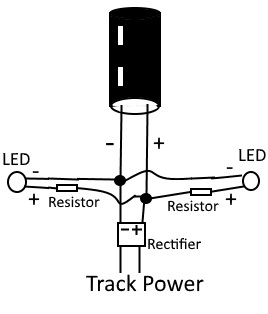
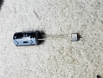
Here is a shot of my coach lighting kit on eBay. I designed this kit for my own use because I wanted to light my coaches with LED's on DC (either direction) and DCC. I also wanted a "keep-alive" function to minimize flicker over dead spots. It comes with (2) LEDs, (2) matching resistors, a capacitor, and a bridge rectifier. The purposes of each component is outlined below.
LEDs: source of light
Resistors: drop the track power voltage down to a voltage the LEDs can handle
Capacitor: Keep the LED's lit (somewhat) when the coach runs over a dead spot in the track.
Bridge Rectifier: take track voltage and change it to a specific polarity.
Tools required: Soldering iron and solder, wire stripper, glue or some other way to attach the LEDs to the coach
Materials required: 30 AWG wire, passenger coach with track contacts/pick-up trucks.
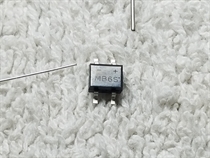
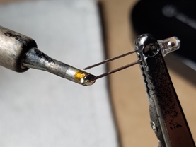
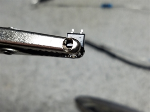
Here is a close-up of the rectifier. It is marked with polarity on its output, which must be propoerly connected to the rest of the components listed above.
The LEDs have specific polarity. The longer of the two leads is the annode (positive). I usually put my resistors on the positive, but you could use the cathode (negative) instead. As long as the resistor is on one of the leads.
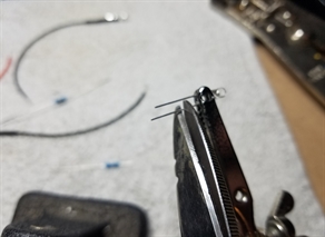
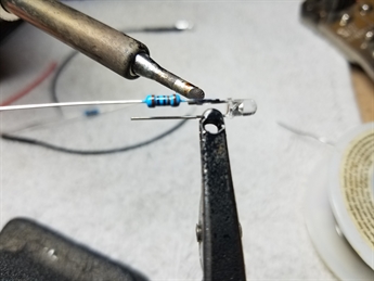
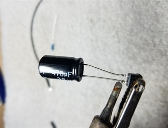
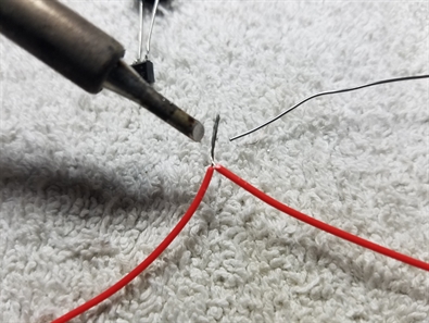
This picture shows me cutting the positive in preparation for attaching the resistor. I also cut down the resistor lead and weld the two cut ends together.
This picture shows me cutting the positive in preparation for attaching the resistor. I also cut down the resistor lead and weld the two cut ends together.
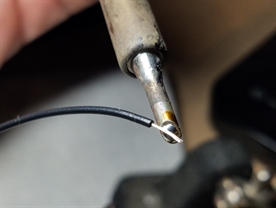
Strip some wire and "tin" the ends. "Tin" is to saturate the metal with solder before welding to its counterpart. This procedure should be done to all metal parts before welding.
Weld the resistor to the LED...
...the wires to the LED and resistor...
...and finish with some 2mm heat shrink. Repeat the process with the second LED and resistor.
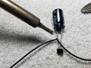
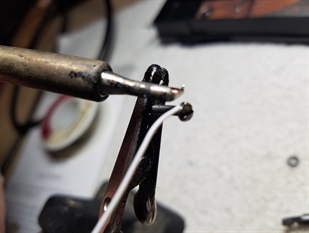
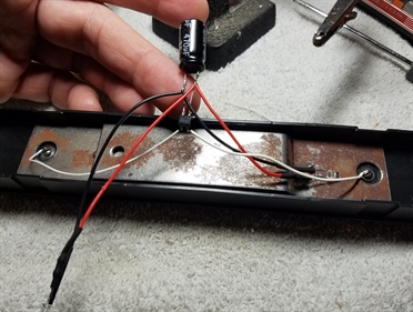
All the components have polarity, so you must match them properly. Fortunately, it is easy to do so as long as you pay attention. Here you can see the rectifier and the capacitor oriented properly before attaching. You will need magnification and plenty of light to see the polarity on the rectifier.
I hold the smallest part, the rectifier, in a clamp to make things easier. I then "tin" and weld the capacitor to it, making sure to match the polarity.
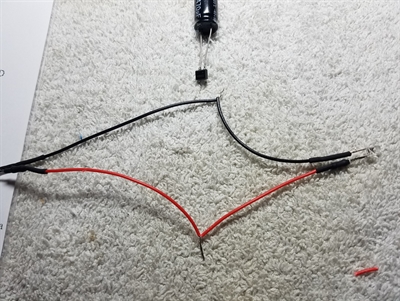
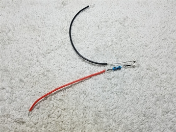
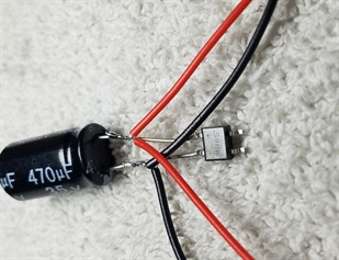
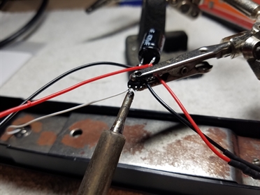
Take the two prepared LED assemblies and twist the wires together, again being aware of polarity. Then weld the connections to prepare for attachment to the rectifier/capacitor.
Weld the wires to the capacitor leads. I like doing it this way, rather than trying to attach the rectifier, capacitor, and LEDs at the same time, which can be cumbersome. No need for heat-shrink or other insulation, the wires are held apart by the capacitor leads.
Adding the Coach Lighting Kit to an Athearn Blue Box Coach
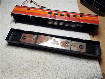
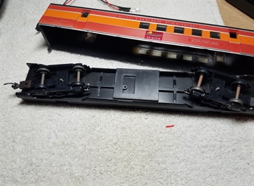
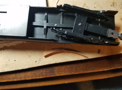
Here is a typical Blue Box Athearn coach with pick-up wheels, but lacking the rest of the contacts to do the job. The wheels are a little rusty and there are no actual "wipers", so we will be adding some.
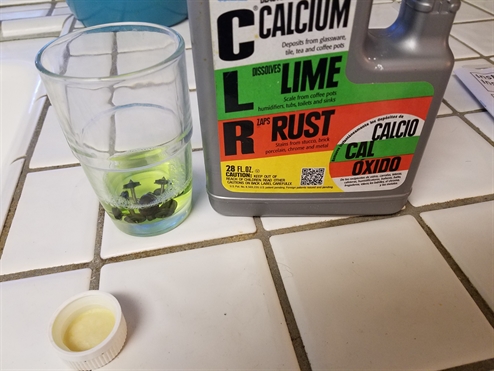
I need to remove the surface rust from the wheels, so a soak in some CLR will do it. 20 minutes or so, then rinse and wipe down with some pressure using paper towels.
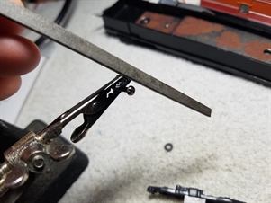
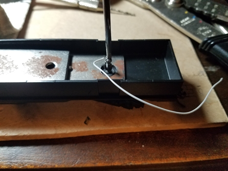
Take the screw that holds the truck on the body and file a corner. Use some solder flux and "tin" the corner of the screw, and weld a wire to it.
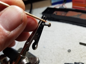
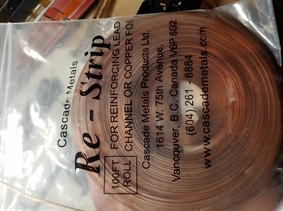
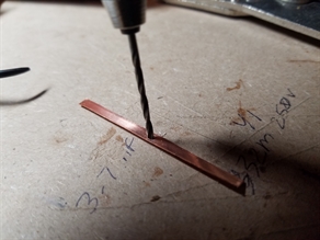
I bought some copper "re-strip" wire for use in making contact wipers. It is not as good as spring steel strips, but it is all I have at the moment. At least it is easy to cut and drill. You can see here I am using a hand drill to make a hole slightly smaller than the screw diameter. It should self-thread nicely.
Assembly has begun. Be sure to not weld contact wires before running the screws into the truck frames. You need the wire to move freely as it twists around with the screwhead. I am not going to screw it in all the way yet, I have to thread it through the copper strip.
Screw is flush with truck frame for the moment while I bend the copper strip to an arc shape.
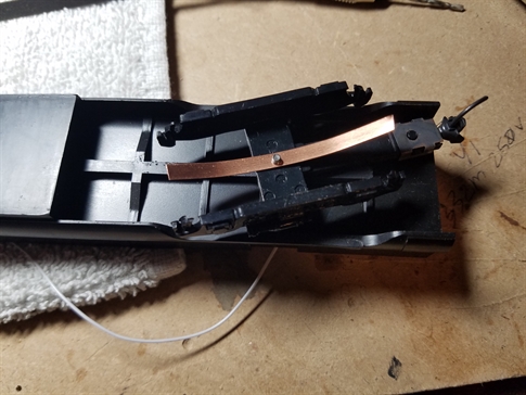
Hold the strip against the truck frame and turn the screw the rest of the way.
Looking good with the wheels in. Trimmed the copper strips a bit.
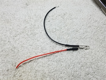
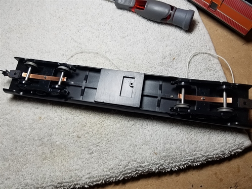
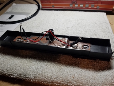
Now it is time to complete the circuit. The two unmarked tangs on the rectifier are not polorized and can be connected either way to the track pick-ups. I bend the capacitor to an upside-down position so I can use hot-melt glue to secure the capacitor top to the metal weights of the coach.
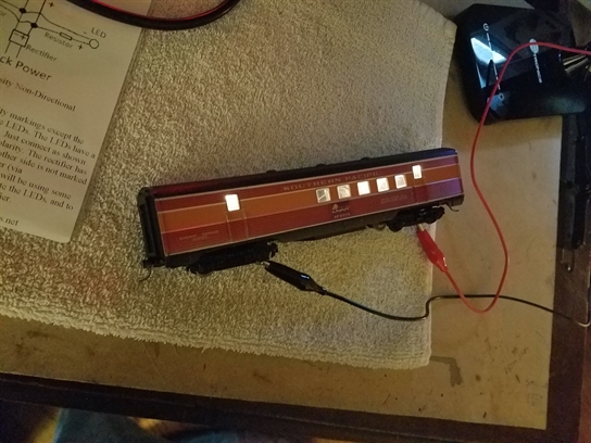
RESULT!
For the purposes of this demonstration, I just put 14v on the wheels for you to see the result. If you are not decorating the inside of the coach, just use some copy paper to diffuse the light, if desired.
For the purposes of this demonstration, I just put 14v on the wheels for you to see the result. If you are not decorating the inside of the coach, just use some copy paper to diffuse the light, if desired.