KATO HM-5 Remotor in an Athearn Blue Box Diesel
My KATO HM-5 motor mount
Available in my eBay Store
Available in my eBay Store
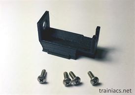
Parts: JM-5L Mount and (4) #4-40 screws
Fits: All Athearn diesels GP38 and larger, RTR RS3 and larger
(i.e. does not fit SW or any other diesel with smaller Athearn motor. Fits GP9,GP15,GP18,GP20,etc. with frame modification)
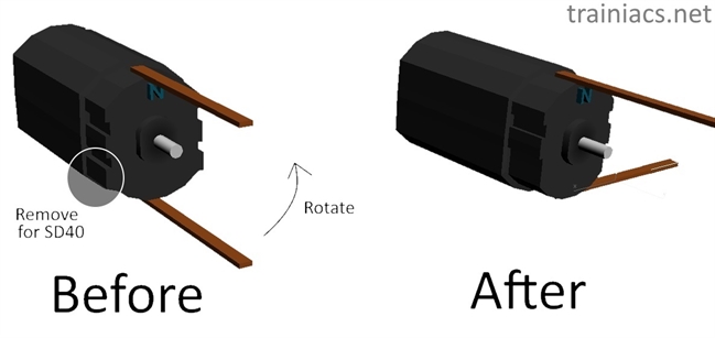
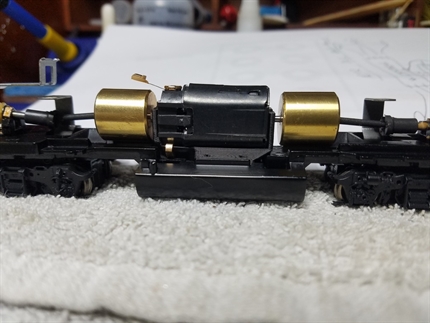
1. Modify Motor. Rotate electrical connection tab on motor to one side as shown. When mounting in a BB SD40 frame, I usually shave the motor a bit to fit properly. There is an “N” printed on the top of the motor, so use that as a guide to ensure proper voltage/direction.
Fits: All Athearn diesels GP38 and larger, RTR RS3 and larger
(i.e. does not fit SW or any other diesel with smaller Athearn motor. Fits GP9,GP15,GP18,GP20,etc. with frame modification)
1. Modify Motor. Rotate electrical connection tab on motor to one side as shown. When mounting in a BB SD40 frame, I usually shave the motor a bit to fit properly. There is an “N” printed on the top of the motor, so use that as a guide to ensure proper voltage/direction.
2. Slide motor into mount at angle (note flanges on motor that match with mount). Should be oriented as shown, with "N" at the top. Lower front of motor and carefully seat notched flange into notched hole (flex the plastic of the mount out with a fingernail or flat-head just enough to slide motor in, then press it back over motor flange). Note: the mount is made from plastic, so if it breaks, simply glue back together. I test fit every one before I send it out, they never break on me but you never know.
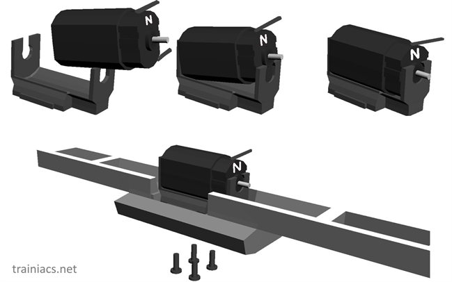
3. Place motor and mount into loco frame (SD40 frame pictured). If you have a smaller GP Loco (GP7-20), you will have to grind the frame down to fit. This is because of the dimensions of the HM-5 motor and the clearances required to mount it securely.
4. Insert screws until mount is secure. DO NOT OVERTIGHTEN.
Other Notes
DC operation: If you don’t need to isolate the motor (DC operation) bend bottom electrical tab as needed to sandwich between the mount and the frame. Scrape some paint away from the frame where the copper contacts the frame to provide a good electrical contact.
For DCC or other isolated applications: what I usually do is cut the motor's bottom electrical contact in half (or so) and use the cut-off half to sandwich below the mount to provide the frame contact. For some locos (like the BB SD40-2) the frame is right up against the motor's lower electrical contact, so use electrical tape or heat shrink where it touches the frame to make sure it stays isolated.
Transferring over the flywheels
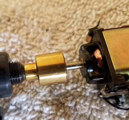
The shafts of a stock Athearn motor are 3.175mm (1/8”) but the HM-5 motor shafts are only 2mm, so to reuse the flywheels and shafts a spacer/reducer is necessary. Another option is the HM-5 motors are available with flywheels pre-installed. I prefer to transfer the flywheels. I found some 1/8" outside diameter aluminum tubing that has close to the correct inside diameter. Read on to see my technique. I use two special tools to make life easy: a small gear puller and a benchtop drill press.
Flywheel Removal
Removing the flywheels from the Athearn motor can be tricky. After repowering dozens and having some real chanllenges (especially with RTR locos), I found the perfect tool on Amazon.com for removing them: the "Great Planes" gear puller tool GPMR2410. This was designed for pulling gears off of other models, such as model planes and cars.
The following pictures show how I removed an unusual flywheel from a RTR RS-3. I could not get this friggin' flywheel off with any of my regular techniques (heat, vice, 1/8" pin, hammer, etc).
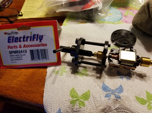
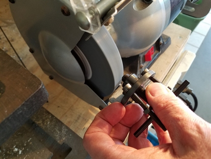
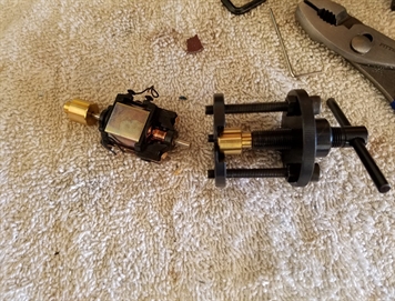
A picture of the tool, and it's label tab indicating model number, brand, etc. The RS-3 motor and attached flywheel seemed to fit perfectly in the tool. Once seated against the pin inside the flywheel, the first crank of the tool is the hardest. I think Athearn might have glued these on.
Here you see the tool head bottoming out on the flywheel before the motor shaft was pushed out of the flywheel all the way (the tool head is the threaded part). There is a "pin" mounted inside the threaded head that is inside the flywheel and is supposed to push the motor shaft out. It is not long enough to finish the job.
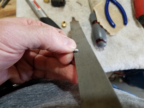
My solution is to grind the head back so there is more length of the pin sticking out. The pin comes out via a lock screw, then I reversed the head in the tool and started to grind the beveled part down. The head needs to be inside the frame of the tool so I can back it out through the threads to restore the threads that I grind down. It's a common technique used by those who cut or grind threaded metal to leave a nut on the material for screwing off the ground end to restore the threads.
Bingo!
Flywheel Installation on a Kato HM-5
As mentioned earlier, I found some aluminum pipe with an outside diameter of 1/8" (I hope to perfect the technique of making spacers out of this material so I can offer it with my motor mount for a turn-key solution). After I cut a small piece off the pipe, I file the flashing off of one end so I can hammer it into the flywheel.
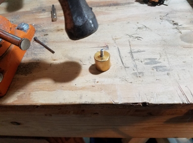
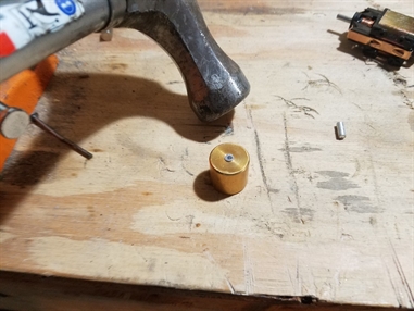
Tap the spacers into the flywheels. The tapping actually occured on the anvil of a vise.
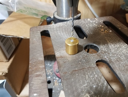
The inside needs honing, especially after hammering it. A drill press with a 2mm bit is the only way I have found to accurately drill out the inner hole. Fun story: I was having trouble with wobbly flywheels until I discovered my press' table was ever-so-slightly off.
The flywheels fit pretty easy, sometimes too easy in fact. It's not something a dab of CA glue can't fix. Make sure before gluing that you test fit the whole drive train to get the flywheel placement correct.
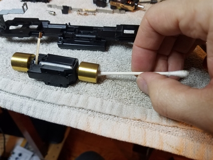
Don't forget to clean any shavings out of the hole! Q-tips are perfect for this.
Install the motor and wire it to the trucks and give it a test on a DC track before continuing on with your project.